|
|
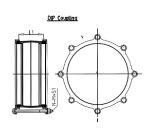
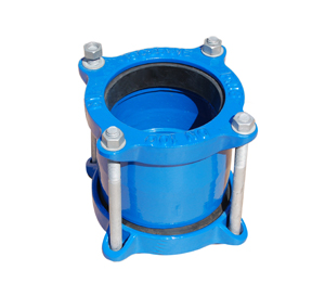
| DIP Coupling |
|
| DIMENSIONS (mm) |
| DM |
OD |
N |
M |
L1 |
S1 |
L2 |
S2 |
Flange standard |
| 80 |
98 |
4 |
1/2" |
100 |
175 |
70 |
110 |
PN10+PN16+BS10/E |
| 100 |
118 |
4 |
1/2" |
100 |
175 |
70 |
110 |
PN10+PN16+BS10/E |
| 150 |
170 |
4 |
1/2" |
100 |
175 |
75 |
120 |
PN10+PN16+BS10/E |
| 200 |
222 |
4 |
1/2" |
100 |
175 |
75 |
120 |
PN10+PN16+BS10/E |
| 250 |
274 |
6 |
1/2" |
100 |
175 |
90 |
130 |
PN10+PN16+BS10/E |
| 300 |
326 |
6 |
1/2" |
100 |
175 |
90 |
130 |
PN10+PN16+BS10/E |
| 350 |
378 |
8 |
5/8" |
150 |
230 |
100 |
135 |
PN10+PN25+BS10/E |
| 400 |
429 |
8 |
5/8" |
150 |
230 |
100 |
135 |
PN10+PN25+BS10/E |
| 450 |
480 |
10 |
5/8" |
150 |
230 |
100 |
135 |
PN10+PN25+BS10/E |
| 500 |
532 |
10 |
5/8" |
150 |
230 |
100 |
135 |
PN10+PN25+BS10/E |
| 600 |
635 |
10 |
5/8" |
150 |
230 |
100 |
135 |
PN10+PN25+BS10/E |
| 700 |
738 |
12 |
5/8" |
150 |
230 |
100 |
135 |
PN10+PN25+BS10/E |
| 800 |
842 |
12 |
5/8" |
150 |
230 |
100 |
135 |
PN10+PN25+BS10/E |
ISO2531:1998 or BS EN 545:2002
USE: Connect Ductile Iron Pipe (DIP)
|
| MATERIAL SPECIFICATION |
| Bolt & Nuts: Hot Dip Galvanized or Stainless Steel |
BS 729:1971, ISO 1461 |
| Sleeve: Ductile Iron |
BS2789:1985 Grade 420/12 |
| Gland (End Ring): Ductile Iron |
BS2789:1985 Grade 420/12 |
| Rubber Gasket: SBR, EPDM |
BS 2494:1990 Type W |
| Coating: Fusion Bonded Epoxy or Wet Epoxy |
DFT 250ūm Min. |
|
|
|